July 26, 2022
NSX-T Tier-1 Service Router (SR) Placement
NSX-T Tier-1 Gateways, Failure Domains, Standby Relocation, and Pre-emption.
A few weeks ago I was asked by a client if Standby Relocation worked in conjunction with Failure Domains to enable ‘smart’ Tier-1 Service Router placement. This post will attempt to explain the behaviour in various scenarios, including:
- Tier-1 Active SR failure with Standby Relocation disabled
- Tier-1 Active SR failure with Standby Relocation enabled
- Tier-1 Active SR failure with Standby Relocation and Pre-emption enabled
This post will first provide an explanation of each of these features to explain when and why they may be needed, then walk through configuration of Fault Domains, lastly performing various failure scenario tests.
The video below covers the foundations of logical routing and how a stateful service can impact the data plane.
Failure Domains, Standby Relocation, and Pre-emption
Failure Domains
Failure Domains provide a logical way to group Edge nodes in an Edge Cluster. They are useful when the VMware NSX environment has Tier-1 gateways that are configured with stateful or centralized services.
A Failure Domain provides a method to logically place the active SR of a Tier-1 gateway on a pre-determined Edge node, in an Edge cluster. If a decision is made that it does not matter which Edge node the Active SR resides on, then this feature is not required in your environment.
If your organization requires awareness and would like to deterministically place the active SR on a particular Edge node, then you should configure Failure Domains. In most situations, this feature is used in multisite, however, there may be other use cases for it. The NSX Reference Design Guide provides an explanation on this feature as well.
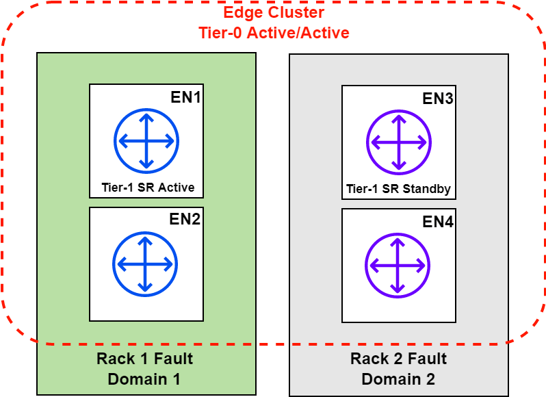
This blog post will utilize Failure Domains as depicted in the diagram below.
Standby Relocation
When enabled, this feature relocates the Standby SR. If a failure was to occur on the Edge node hosting the active SR (EN1 in this case), the standby SR (EN3) will become active. Standby relocation creates / assigns the standby on a remaining Edge node in the cluster. If there are only two Edge nodes in a cluster and an Edge node has failed, this feature will not have any remaining Edge nodes to create the Standby SR on. The diagram below shows an example of Standby Relocation in effect with a four node Edge cluster.
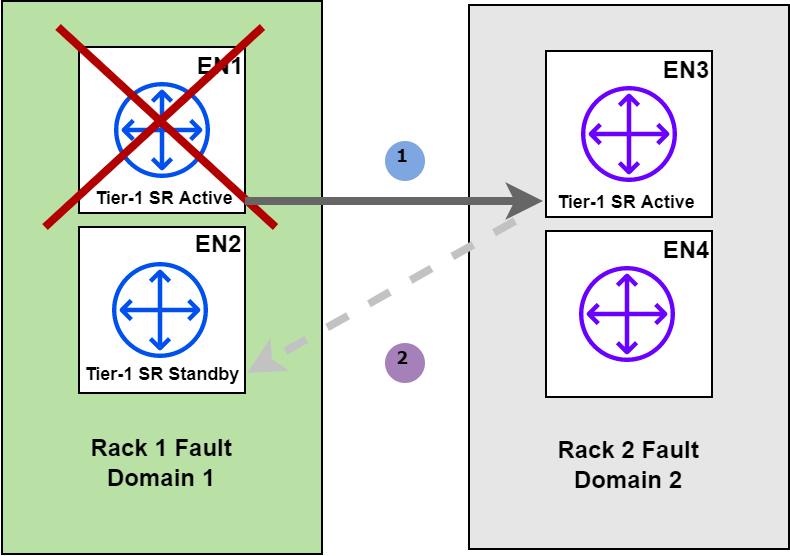
The image above depicts a failure on EN1, which in this case is hosting the Active SR for the Tier-1 gateway. The SR is made active on EN3, however, since EN3 previously hosted the standby SR, it now needs to be moved. After a certain amount of time (defined by the Standby Relocation timer, discussed later), the SR is then moved onto one of the remaining Edge nodes. In this example, it will be moved to EN2, this way both the active and standby SR’s are not placed within the same Failure Domain.
Pre-emption
This feature is not new to the networking domain. Put simply, if the preferred Edge node with the active SR fails, the standby takes over. If the preferred node becomes active again, it will retake ownership of the SR and become active once again. If pre-emption is not enabled, the active SR will remain on what was previously the Edge node with the standby SR (EN3 in the diagram above).
There are two modes of operation for this feature:
- Pre-emptive: feature is enabled.
- Non Pre-emptive: feature is disabled.
Failure Domain Configuration
The diagram presented in the Failure Domain feature section represented the configuration that will be applied in this section. Below is a summary of what will be configured:
- A single Edge cluster with 4 Edge nodes
- Two Failure Domains, Failure Domain 1 is preferred
- Failure Domain 1 will have EN1 and EN2
- Failure Domain 2 will have EN3 and EN4
Create the Failure Domains
I will be using postman to make the required API calls in this section. API is the only method currently available to configure Failure Domains.
Create Failure Domain 1
curl --location --request POST 'https://nsx.region1.shank.com/api/v1/failure-domains'
--header 'Authorization: Basic YWRtaW46UEBzc3cwcmQxMjMh'
--header 'Content-Type: application/json'
--data-raw '{
"display_name": "FailureDomain1",
"preferred_active_edge_services": "true"
}'
If you are importing the request into postman or any other tool, you will have to update the authorization section to suit your environment.
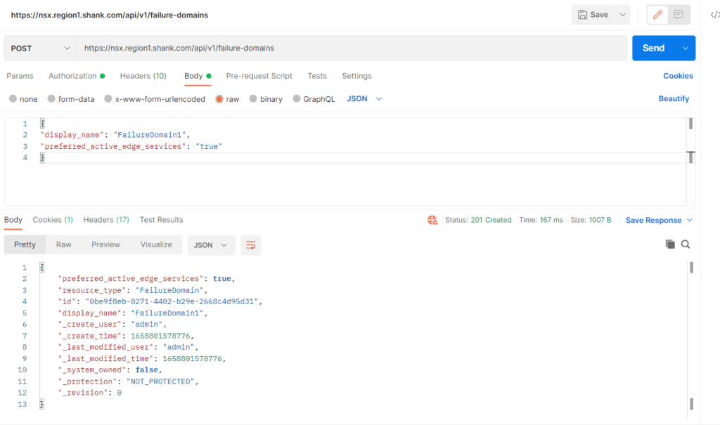
Notice the field “preferred_active_edge_services” is marked as true.
Create Failure Domain 2
This step will be very similar to the previous Failure Domain that was created, however, this time the active edge services flag will be set to false.
curl --location --request POST 'https://nsx.region1.shank.com/api/v1/failure-domains'
--header 'Authorization: Basic YWRtaW46UEBzc3cwcmQxMjMh'
--header 'Content-Type: application/json'
--data-raw '{
"display_name": "FailureDomain2",
"preferred_active_edge_services": "false"
}'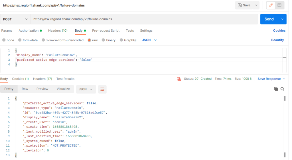
Below are the results of a GET query to the same URI.
{
    "results": [
        {
            "preferred_active_edge_services": false,
            "resource_type": "FailureDomain",
            "id": "0ba482ba-409b-4277-848b-07316adfce57",
            "display_name": "FailureDomain2",
            "_create_user": "admin",
            "_create_time": 1658801868498,
            "_last_modified_user": "admin",
            "_last_modified_time": 1658801868498,
            "_system_owned": false,
            "_protection": "NOT_PROTECTED",
            "_revision": 0
        },
        {
            "resource_type": "FailureDomain",
            "id": "4fc1e3b0-1cd4-4339-86c8-f76baddbaafb",
            "display_name": "system-default-failure-domain",
            "_create_user": "system",
            "_create_time": 1658308295808,
            "_last_modified_user": "system",
            "_last_modified_time": 1658308295808,
            "_system_owned": true,
            "_protection": "NOT_PROTECTED",
            "_revision": 0
        },
        {
            "preferred_active_edge_services": true,
            "resource_type": "FailureDomain",
            "id": "0be9f8eb-8271-4402-b29e-2668c4d95d31",
            "display_name": "FailureDomain1",
            "_create_user": "admin",
            "_create_time": 1658801578776,
            "_last_modified_user": "admin",
            "_last_modified_time": 1658801578776,
            "_system_owned": false,
            "_protection": "NOT_PROTECTED",
            "_revision": 0
        }
    ],
    "result_count": 3
}
Assign Edge Nodes to Failure Domains
Now that the Failure domains have been created, the Edge nodes must be assigned to them. This section will demonstrate how to add a single Edge node into a Failure domain. The process will have to be repeated for the remainder of the nodes.
To assign nodes to Failure Domains you will need:
- Edge Transport Node UUID’s – there are a couple of ways to get this, the easiest would be to navigate to the NSX Manager user interface and copy these details.
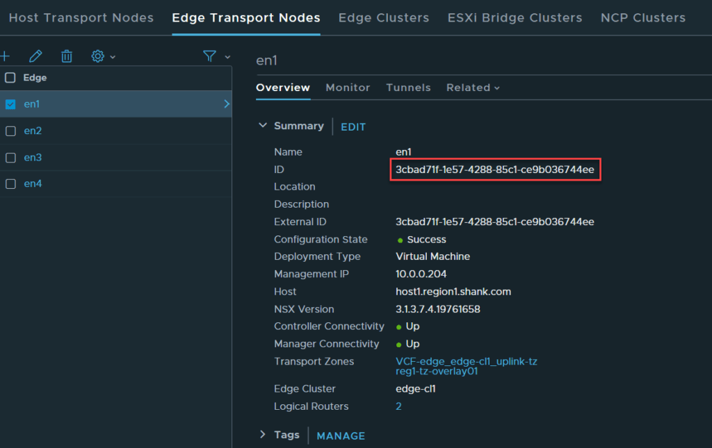
- Failure Domain UUID’s – the output from the previous GET command has an ID section that has this information.
API Call to Assign the Edge Node
Once again in Postman, issue a GET command to /api/v1/transport-nodes/<IDofTransportNode>. You should get a response similar to the below image.
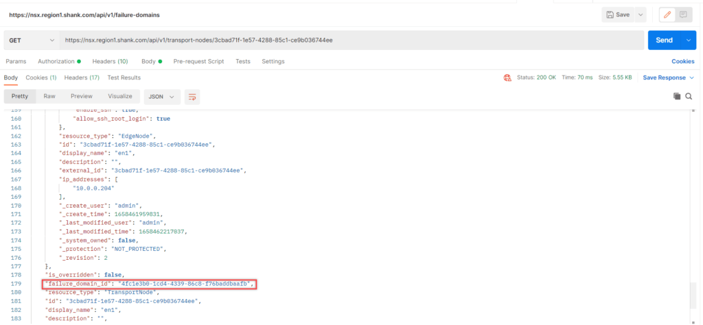
Now change the request from GET to PUT, notice the field called “failure_domain_id” it is currently set to the system Failure Domain, update it to reflect the correct Failure Domain ID for Failure Domain 1.
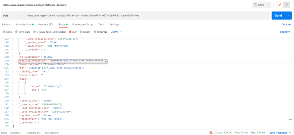
If you want to check that it has worked, you can issue the initial GET command and check the failure_domain_id field has correctly updated. Repeat this process for each remaining Edge node, ensuring the nodes are placed into their respective Failure Domains.
API Call to Configure Node Allocation Based on Failure Domains
Issue the queries below to ensure Edge nodes are placed into their respective Failure Domains correctly.
First, issue a GET command to /api/v1/edge-clusters/<edge-cluster-id> – the Edge cluster ID can be obtained in from the UI, as you did previously for the Edge nodes.
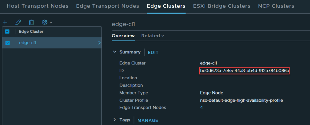
Copy the output into the body and change the request from GET to PUT, as can be seen in the image below.
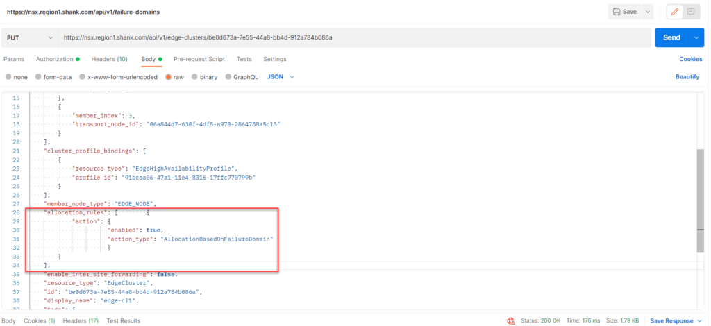
Note: If you skip this last step, the Active SR may not be correctly placed.
These instructions can also be found on the VMware NSX Documentation site.
Create a Tier-1 Gateway with Services
Navigate to Networking -> Tier-1 Gateways -> Add Tier-1 Gateway. Ensure you attach an Edge cluster so the gateway is placed into Active-Standby.
Scenario Testing
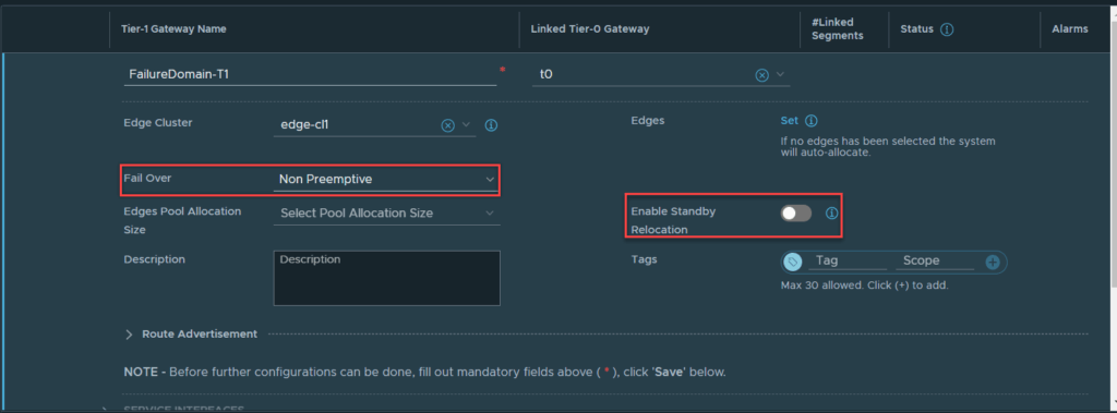
Scenario #1 – Active-Standby – Standby Relocation Disabled and Pre-emption Disabled
Below is the configuration of the Tier-1 Gateway.
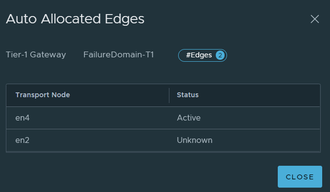
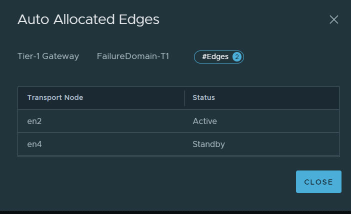
Once it is created, click on the hyperlink next the Edges labelled “Auto Allocated”. This will display the Active and Standby Edge nodes.
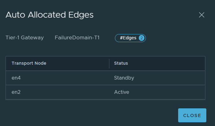
Per the image above, you can see that EN2 is active for the SR and EN4 is standby, which means the active SR is in Failure Domain 1 and the standby SR is in Failure Domain 2.
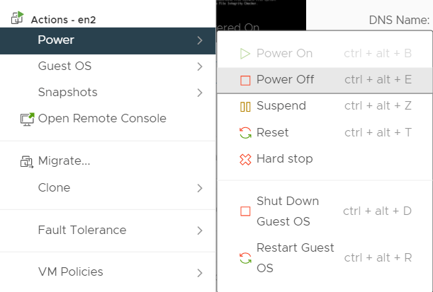
Simulate EN2 (Active SR) Failure
To simulate the node outage, en2 will be shutdown in vCenter.
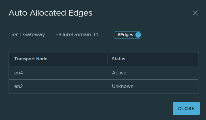
If you check the Edge nodes on the Tier-1 gateway again, you should see that the active SR has failed over to the standby Edge node.
No matter how long you wait, the standby will not be moved / created on a remaining Edge node because standby relocation was not enabled. If EN2 comes back online, the active SR will remain on EN4, because pre-emption was not enabled.
Scenario #2 – Active-Standby Tier-1 – Standby Relocation Enabled and Pre-emption Disabled
As Standby Relocation was enabled for this test, it makes sense to now address Standby Relocation timer configuration.
The default timer for Standby Relocation is 30 minutes and is applied as part of the Edge cluster profile, the minimum it can be set to is 10 minutes.
The default profile can be found in System -> Fabric -> Profiles -> Edge cluster profiles. The system generated profile cannot be modified, so you will need to create a new profile.
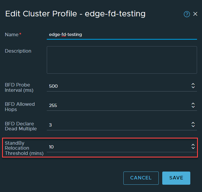
There are other BFD related settings that can be configured here, but I will not be covering those in this post. Once the profile is created, it needs to be applied to the Edge cluster.
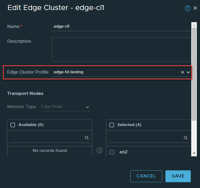
Navigate to System -> Fabric -> Nodes -> Edge Clusters. Edit your Edge cluster, select your newly created Edge cluster profile and click save.
The Edge node with the active SR (EN2) will be shut down again, as per the steps displayed in the previous section, they will not be repeated.
Immediately EN4 takes over as the active Edge node for the SR.
Now Standby Relocation should move the standby SR.
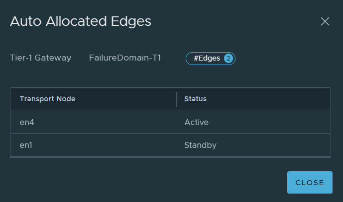
We can see here that the standby has been moved to EN1, where in the previous example it was never moved to another Edge node in the event of EN2 failing and status remained as Unknown. This is a useful feature and would work successfully, however, the customer requirement was for the active SR to be active on specific Edges in Failure Domain 1, this does not satisfy the requirement.
This scenario simulated EN2 failing, not the entire rack or Failure Domain, which means EN1 is still available.
Scenario #3 – Active-Standby Tier-1 – Standby Relocation Enabled and Pre-emption Enabled
In this scenario, all the features that have been discussed have been enabled. The image below shows the current placement of the SR.
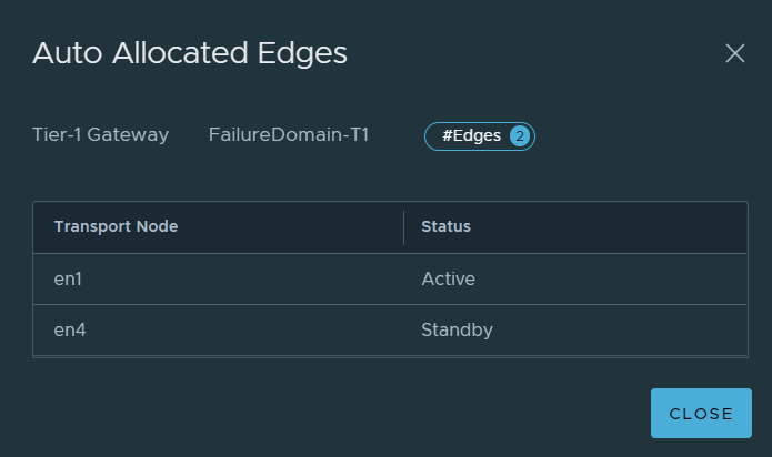
EN1 will now be shutdown to simulate the Edge node outage, EN4 becomes active.
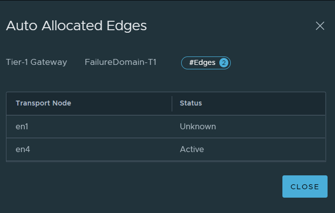
As you would expect, EN1 moves into an unknown state. Once the Standby Relocation timer ticks over, the standby will be recreated, as can be seen in the image below.
What you will also notice is, the standby SR was created, however, pre-emption ensured the active SR was placed on an Edge node in Failure Domain 1 (EN2), and the standby was moved to Failure Domain 2 (EN4). So this configuration satisfied the customer requirements.
You must ensure you are aware of the caveats of enabling pre-emption (during failover and failback), whereby there could be some intermittent packet loss.
Conclusion
The customer requirement of having smart Tier-1 Service Placement was possible with a combination of Failure Domains, Pre-emption, and Standby Relocation. Each scenario demonstrated in this article displayed the expected behaviour for each configuration, both separately and finally in combination to achieve the desired outcome. Feel free to reach out or leave a comment if anything is unclear. An alternative to achieving a similar outcome would be to manually allocate Edge nodes when creating Tier-1 gateways, however, this is a manual process.
Check out my other NSX articles here.